

Fast-Tracking 5G & Advanced Driver Assistance Systems (ADAS)
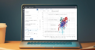
Roadmap from 1G to 5G-ADAS From the past few decades, the world has witnessed many versions of a cellular network, 1G version was a basic voice communication system that supported only Analog modulation. The flavour of data connectivity was present in the second version that used in digital technology. 3G version flavoured highly improved data connectivity using technologies such as Wideband Code Division Multiple Access (WCDMA) and High-Speed Packet Access (HSPA). Currently, 3G is the largely sold version of cellular networks around the globe although the next 4G network version is closing the gap quickly. The third and fourth generations (3G and 4G) of mobile communication technologies are widely deployed, providing voice and mobile broadband as their main services. Presently the world is enjoying the pleasure of 4G that uses orthogonal frequency division multiplexing (OFDM) technology to provide bandwidth of 20 MHz with Multiple Input and Multiple Output (MIMO) antenna transmission Technology. The world is progressing rapidly towards next-generation cellular communication and is on the verge of entering into the 5G era, with completely new infrastructure and technology. A challenge of today’s 5G research is in the waveform frequencies that are being used around the world as signals will suffer from more noise at these frequencies. And these noise levels can be minimized to some extent by performing proper filtering at waveform level but can be reduced majorly by applying proper signal processing technique at the transmit antenna side and receive antenna side. FBMC is an upgraded version of OFDM, which offers benefits such spectral efficiency and resistance to multipath with zero inter-carrier interference and is expected to come with 5G. There is a rapid increase in demand for high definition multimedia streaming around the world. The currently utilized microwave frequencies won’t be sufficient to meet this demand due to a shortage of bandwidth. We need up-gradation to mm Wave frequency bands that provide a larger bandwidth to meet this demand. Several GHz of the spectrum at mmWave frequencies provide an abundance of bandwidth to support GBPS data rates. This abundance in bandwidth helps to incorporate large array that provides high directivity to combat path loss and reduced interference. We can successfully transmit a huge amount of data known as BIG DATA by utilizing these spectrums. The signal at these higher frequency band suffers higher path loss and rain attenuation due to which it is not suitable for outdoor communication. The wavelength of mmWave signal is very small due to which it becomes practicable to embed the multiple numbers of antennas that will direct the signal into highly concentrated beams with sufficient gain to master propagation loss. This process of sharpening of beams is called beam formation, where signals will be added constructively at some point in space. Upcoming 5G systems are predicted to introduce these profound technologies. Why 5G? The urge for data usage is increasing day by day globally and the existing LTE network needs to be improved with LTE-Advanced that provides bandwidth till 100MHz. Even though it is continuously updated through new releases, and with LTE Advanced Pro Release being the latest one, the development of the fifth generation has been initiated. After a few more year’s LTE-Advanced technologies won’t be sufficient to satisfy the increasing data urge around the world and there will be a need for the new version of a cellular network that can satisfy the data requirements in coming years. 5G network is visualized to simplify the burden on current cellular infrastructure by offering significantly higher data rates through increased channel bandwidth. 5G communication system is expected to exploit the spectrum band at millimetre-wave (mm Wave) frequencies. But the mobile communication at these mm Wave spectrum band is far more complex than the current frequencies that are being used around the world as signal suffers higher propagation loss. Antennas for next-generation 5G will make use of shorter element size at high frequencies to incorporate beam formation capabilities. This helps to increase the capacity of the cellular network by improving the signal to noise ratio (SNR) and maintain an optimal BER (Bit Error Rate) at mm Wave frequencies. 5G mobile network offers a vision of “everything everywhere and always connected” which will make use of microwave and Millimetre-wave frequencies ahead of 24 GHz. 5G mobile network is surmised of providing minimum data throughput of 1 Gigabit per second. However, due to the increasing demand for higher data rates and larger system capacity, in addition to the emergence of new Internet of Things, ADAS, and safety-oriented mobility use cases, the fifth-generation (5G) is currently being discussed and developed. Different Dimensions of 5G Three Dimensions of 5G are: Massive Machine-Machine Communication (mIOT) Ultra-reliability-ADAS systems and Enhanced Mobile Broadband (eMBB) A key scenario for 5G, IoT, and ADAS System has connected mobility as shown in the above image, which utilizes vehicular communication for such things as infotainment, safety, and efficiency. While these requirements are already in the scope of 5G standardization, the ability to meet the requirements in practice is more important than ever because of the criticality of the safety-oriented connected mobility use cases. These cases rely on vehicular communication for such capabilities as platooning, cooperative awareness, and self-driving cars. CADFEM UNIQUE 5G ADAS SYSTEM PROTOTYPING Simulation enables innovative ideas, that can push products beyond their traditional limits, to be tested and realized without the burden of prototype costs and time. When engineering simulation software made its debut nearly 50 years ago, early adopters quickly distinguished themselves from those companies who were slower to recognize and embrace its potential. Tomorrow, it will be part of the toolbox for every engineer. As we push for ever-smarter and more efficient product designs like 5G, we can no longer afford to only look at a single aspect of performance or alone part in isolation. In the past, engineering simulation teams were likely to isolate just one critical physics. Today, thanks to improvements in simulation software, hardware, and processing speeds, it has become much easier for engineers to study
Integrated Functional Safety and Safety of the Intended Functionality Analysis using Ansys Medini Analyze

Functional Safety (FuSa) standards such as ISO 26262 have proved their immense importance to make the electronic components more reliable in today’s cars by delivering consistent performance and reducing critical system failures. However, with the rise of ADAS features, the autonomous driving capabilities in vehicles come with an even higher engineering challenge regarding safety and reliability. Sensors, and other components that are working as a designed part, are falling short of capabilities when running in real-time scenarios resulting in dangerous conditions. To address these types of challenges, a new standard safety of the Intended Functionality (SOTIF), ISO 21448 safety standard, will be soon introduced to identify shortfalls in the performance that can occur even when the system is in failure-free condition. It raises the expectation of every component works as designed, and the design is adequate to work to fulfill its goal with the required performance. On the other side, the new SOTIF standard requires a full range of safety analysis & engineering simulation solutions to enable autonomous vehicle development teams to build flawless performance into their designs right from the early stages of product development. The development team can validate the performance before the vehicle launch in the market. 1.1. What is ISO 21448: Road Vehicles – SOTIF? SOTIF is abbreviated Safety of The Intended Functionality and, in short for ISO/ PAS 21448, applies to functionalities that need a proper awareness of the situation to be safe. This standard concerns how to ensure the safety of the functionality even in the absence of a fault/failure. This is quite in contrast with the traditional Functional Safety (FuSa), which is majorly concerned with the risk associated with system failure. 1.2. How is ISO 21448 related to ISO 26262? ISO 26262 covers the functional safety of the system in the event of failures and has no coverage of safety hazards that result in the absence of system failures. That is the reason ISO 21448 is mandatory in analyzing the situations where ensuring safety without system failure is so complex and complicated. 1.3. Why is SOTIF (Safety of the Intended Functionality) important? In today’s world, vehicle electronics provides features like comfort, communication, and navigation assistance, mission-critical functionality such as steering and braking & more. The global automotive standard helps engineering teams to uncover and address FuSa hazards such as software bugs and hardware failures. Safety stakes have grown even higher, and if a crucial component, let’s say the sensor is not fulfilling its needed functionality or it fails to deliver the performance needed to handle a situation – for example, failing to recognize a pedestrian in the road ahead; the application of ISO 21448 helps us to ensure that the perception algorithm systems (a combination of sensors and software algorithms) will recognize pedestrians in all situations that are part of the Operational Design Domain (ODD). This enables the systems to trigger a safe response in consideration of performance under various ODDs. SOTIF ensures robust design against any disturbances and hazards due to flawed Human-Machine Interactions. Limited contrast resolution images in the presence of blinding sun A Model-Based Workflow Integrating FuSa and SOTIF: To successfully conduct autonomous vehicle development in compliance with both ISO 21448 and ISO 26262 there is a unique model that combines a linear process, V-shaped progression with feedback loops of evaluation and improvement to incorporate the learning and as well as comply with the standard. This model-integrated safety workbench offers all required analysis options for Functional Safety (FuSa), Safety of The Intended Functionality (SOTIF). The following is a step-by-step look at the workflow: Features of the Automated Driving (AD) functionality and the Operational Design Domain (ODD) are defined. From the above-portrayed functionalities, the requirements are derived or transferred from the Original Equipment Manufacturer (OEM) to the supplier. The initial architecture developed on a functional level, and this will begin the integrated FuSa and SOTIF process. Performing the hazard analysis and investigating the causes of potential hazards strengthens the feedback loop to identify the issues during the analysis stage and rectifies them straight from the initial level to the architecture level. Ultimately, this will enhance the requirements and architecture. Engineers execute the refinement and technical concretization of hardware, software, and sensor requirements and solutions, again handled in a model-based way, with a corresponding feedback loop. Performing model-based control software generation will help the engineer to generate safety compliant code, Automotive Safety Integrity Level (ASIL). Moreover, level D. Camera and radar sensor technologies and perception algorithms are validated, sent for evaluation, and improved in a cyclical process until an acceptable performance level for all foreseeable situations has reached. The integrated AD functionality is validated under realistic road conditions to prove that its behaviour is appropriate in every situation. This step includes closed-loop simulation, supported by optimized scenario variation and parameter assignment, as well as automatic identification of “edge cases.” All insights are imported back into the safety tool, closing the validation loop. Hardware, software, and the Electronic Control Unit (ECU) that support AD functionality undergo thorough integration testing on Hardware-In-Loop (HIL) benches. All the insights will get mentioned in a convincing safety case that includes a graphical view of requirements refinement and traceability of all artifacts in the model-based process to demonstrate safety. To maximize efficiency and financial returns, hardware, software, models, requirements, test cases, and other artifacts are available for re-use in future development efforts, typically with extended ODDs or extended functional capabilities. Medini Analyze as a Single Source for meeting SOTIF and FuSa Standards: Ansys Medini Analyze is a software tool, which has been recognized by a different industrial standard for analyzing varied aspects of functional safety, technical safety, and compliance with the standards. Performing SOTIF analysis individually, as a stand-alone activity, will empower the product operational safety analysis and make use of architecture models, vehicle-level malfunctioning behavior analysis, and hazardous event assessments. This can eliminate redundancies and ensure consistency among all the results. Ansys Medini Analyze has enhanced the model-integrated safety approach with new modeling elements for limitations,