Thermal Analysis of Multilayer Printed Circuit Board using Ansys ICEPAK

The electric industry market is projectd to grow rapidly as the electricifcation revolution is changing the automobile and aerospace industries.Due to electrification revolution, the electronics components in the system are increasing. The electronics devices are becoming more and more compact but at the same time the functionality of these electronics related components are also increasing.

Electronics systems can contain various types of parts such as Motherboard,cpu,ram ,capacitors,fans,heat sinks, grills etc. One of the most important component of any electronics system is its motherboard.Thermal management of Motherboard is a an important factor which designer keep in mind while designing any electronics system.

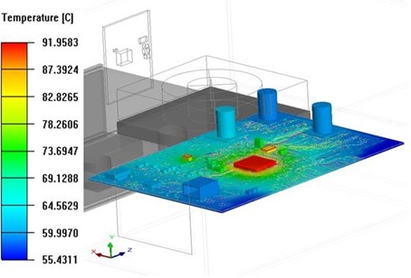
When computer systems performs tasks the data is exchanged between various components and all 
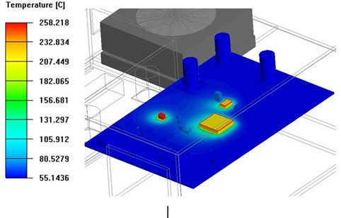
these data travels through printed circuit board so thermal management of pcb is required to decrease 
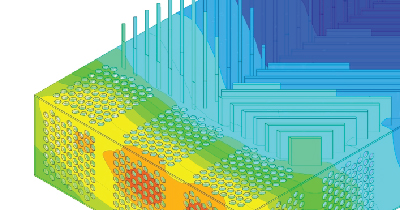
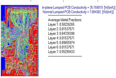
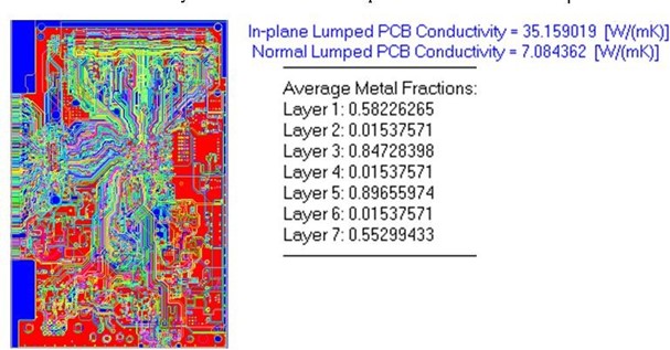
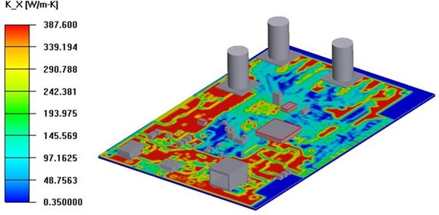
the temperature. Printed circuit board contains copper traces and vias .The simulation of ECAD pcb is very important as copper traces change the metal fraction and the thermal conductivities of pcb resulting in more uniform temperature distribution as compare to the single layered pcb.

Geometry modelling in space-claim:

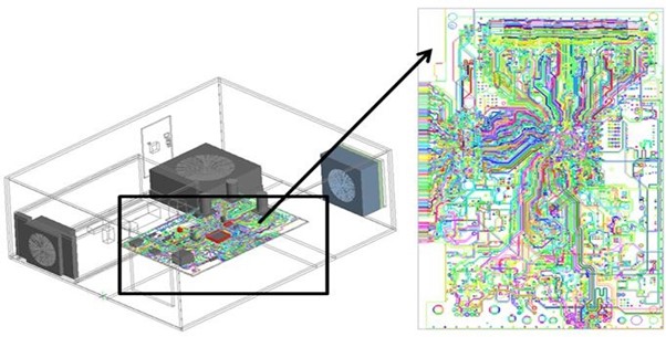
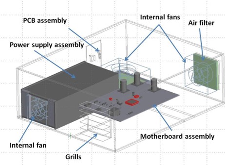
To show the importance of detail modelling of pcb, a generalised elctronics system is designed using Ansys Spaclaim. Please note that this cad design is in no way sponsored by or affiliated with any organization.

We can observe that fans,grills and other components are not modelled here,it is because we are going to modelled fans,grills,resistances in the icepak window. The creation of the model is very rapid from assembly level to the board level.Ansys icepak can create fans,heat sinks, grills,tec,heat 
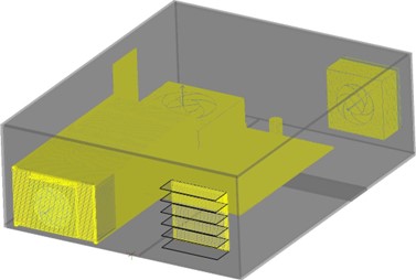
packages,network and all the sorts of things which are present in any electronics components.After modelling the geometry all the parts are converted into icepak obejects using icepak simplification tool.

Modelling Primitive objects in Icepak

After importing the spaceclaim file into Ansys Icepak other primitive objects such as fans,grills,resistances,openings are created inside the assembly using model>create option available in the Ansys Icepak window.

Complete Assembly

Modelling fans

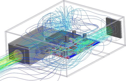
Icepak allow you to model fan without using MRF approach also.Here in the simulation fans curves and fan duty cycles are used to model the fans.Operating RPM and swirl RPM are used as inputs.

Air filters – Air filters can be modelled as resistance.Resistances are modelled as porous domain in Ansys fluent.

Grills – Icepak allows to you to model the grill using pressure loss specification.Pressure loss specification can be given either using opening arear ratio or through pressure velocity curve data.

ECAD Printed circuit board :

Ecad files are imported on to the pcb board. Icepak can read ecad files of various formats such as ODB++,Ansys EDB, Ansoft, Gerber etc. Ansys Icepak reads traces and vias and computes the metal fraction map based on the grid density(rows*column).The model layers seperately option should be turn on to ensure proper mesh connection as shown in figure

Metal Fraction Mapping and thermal conductivities vaulues calculation:

Ansys Icepak computes thermal conductivities values based on the grid density. This thermal conductivity values will be used as input for thermal simulation. Grid density cuts the PCB into various rows and columns and assign thermal conductivities values to each grid.

Mapping Thermal metal fraction and thermal conductivity values

Effort less meshing using Ansys Icepak

Ansys Icepaks’ HD Mesher generates high-quality mesh even for complex geometries. The process of generating the mesh is extremely easy and less time-consuming. Ansys Icepak generates the fluid domain automatically using the cabinet approach and saves a lot of time spent on pre-processing. The overall time required to perform the simulation reduces drastically. Referring to the current case, the overall time spent on meshing and generating high-quality mesh was ~ 15 mins and within 15 mins, 3 mesh trials were performed to identify and optimize assembly size and slack settings. Icepak automatically finds and generates the fluid domain based on empty spaces inside the cabinet/enclosure (with no solid bodies/hollow bodies). Figure 5 and figure 6 shows the mesh created in Ansys Icepak.

PCB assembly mesh

Assembly meshing

Simulation and Post-processing

Electronincs Cooling Simulation of System with Ecad PCB

Simulation of the system is done after giving necessary inputs/ boundary conditions required for running the simulation, such as heat sources wattage, ambient temperature, radiation parameters and material properties description, etc.Figure 7 shows the temperature distribution of the pcb assembly.The maximum temperature obtained for the pcb is ~ 92˚C. Figure 8 shows the velocity streamlines starting from the fan. Figure 9 shows the thermal conductivity distribution of the top layer of the pcb.

PCB assembly temperature distribution

Velocity Streamlines

PCB thermal conductivity distrbution

Electronics Cooling Simulation of System with Ecad PCB

A second iteration is performed by removing the ECAD from the pcb to know the significance of ecad modelling on the pcb temperature distribution.Figure 10 shows the temperature distribution of the pcb assembly. By removing the ecad from the pcb,thermal conductivity of the pcb became 0.34 W/m- K(Fr4) and this led to a very siginificant rise in the temperature of the heat sources.We can also see due to low conductivity,hot spots are getting formed.The maximum temperature location is also getting changed due to change in thermal conductivity value of board at maximum temperature location for second iteration.Table 1 shows the difference between the maximum temperature obtained from the simulation with the without ECAD pcb.The difference in temperature shows the importance of detailed ECAD PCB modelling and simulaion.

PCB temperature distribution without ECAD

Comparison Table

Conclusion:

The present work was an attempt to demonstrate Ansys Icepak’s capabilities in reading and simulating ECAD geometry. The temperature obtained for multilayered ECAD PCB is significanlty lower than the temperature obtained for PCB without trace import. Moreover Ansys Icepak ability to model primitive objects such as fans, grills, resistances, openings ,heat sink can help the engineers to change and create these geometries in the Icepak window very fast.

Ansys Icepak not only saves us from the tedious work of creating fluid domain but its HD mesh algorithm generates high-quality mesh effortlessly. Icepak allows us for a great deal of control on meshing. One can mesh assemblies and subassemblies with different mesh sizes while maintaining an overall coarse mesh for the entire system. Moreover, Ansys Icepak has almost all the popular turbulence models / radiations models which can be used according to the simulation requirement. The combination of these features makes Ansys Icepak a great tool.